


-
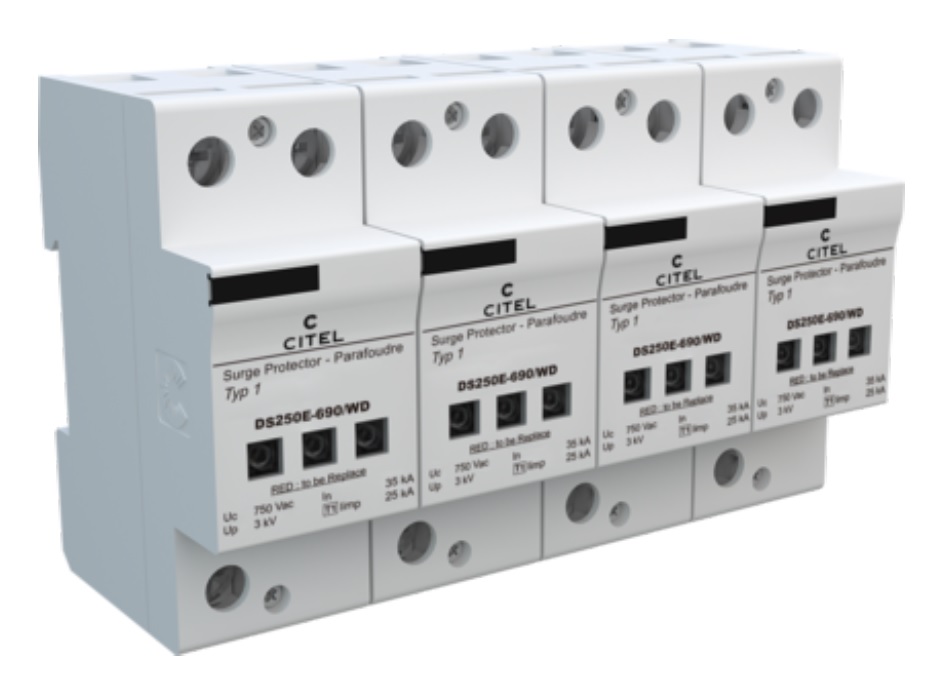
SeriesDS250E
-
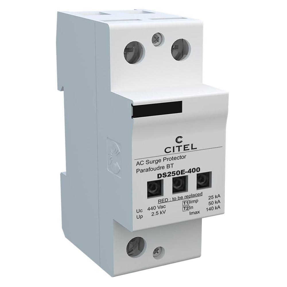
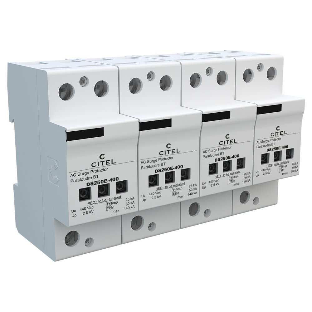
ModelDS250E-400
-
Brand / Made inCITEL / FRANCE
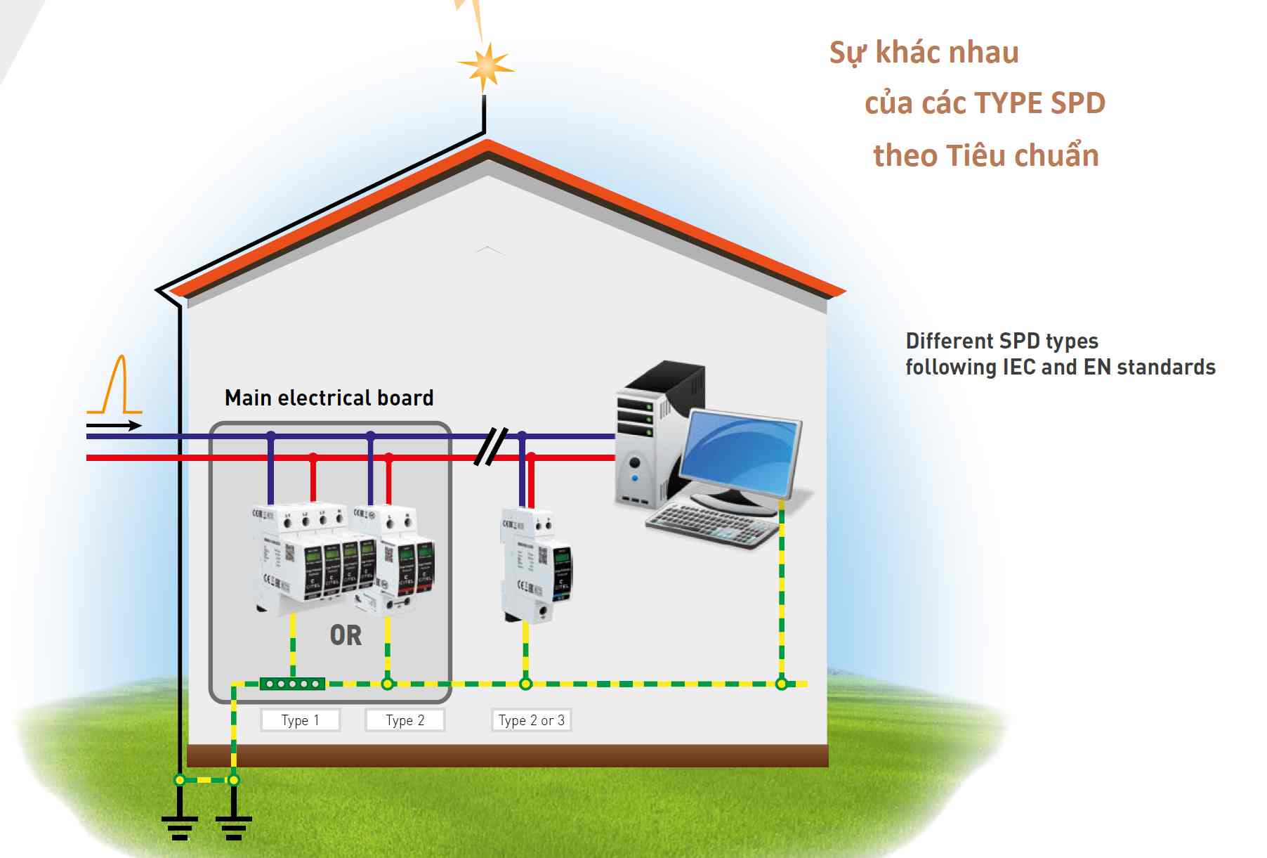
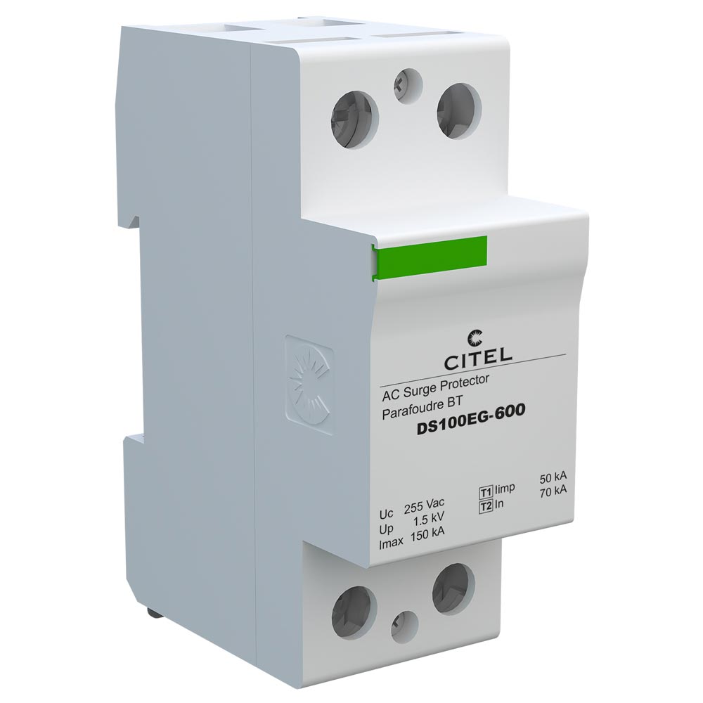
- Type 1 + 2 unipolar surge protector
- Iimp: 25 kA on 10/350µs impulse
- Imax: 140 kA on 8/20µs impulse
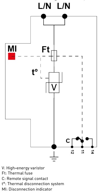
- Internal disconnections, status indicators
- Remote signaling
- IEC 61643-11, EN 61643-11 and UL1449 ed.4 compliance
The DS250E is an extreme duty Type 1+2 designed to protect the entrance of the electrical installation. They are used to protect biphase, 3-phase or 3-phase + neutral networks in common mode or in common and differential mode. The 'Multi-Varistor' technology used allows the best possible behavior for the LV network (no follow-on current). The DS250E is mounted on a DIN Rail and has a double connection for the active conductor, which allows an optimized connection to the network.
Electrical Characteristics
- SPD type (following IEC tests): 1+2
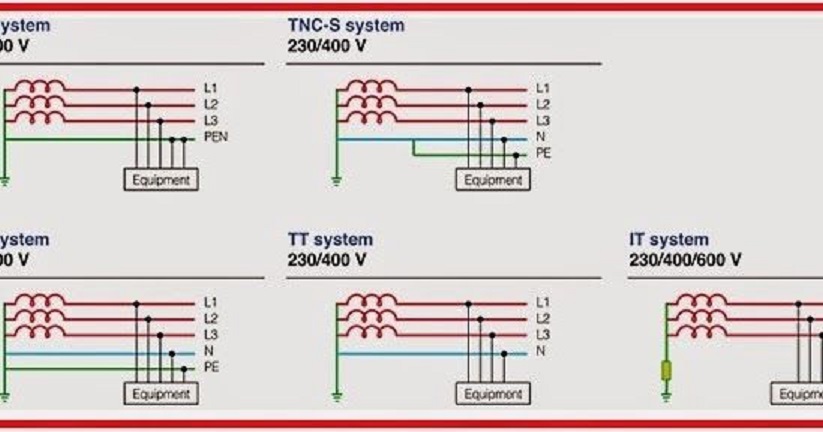
- Network: 230/400 V
- Nominal line voltage Un: 400 V
- Max. AC operating voltage Uc: 440 Vac
- Max. load current(if series connection) IL: 100 A
- Temporary Over Voltage (TOV) Charasteristics - 5 sec (Without disconnection) UT: 580 Vac withstand
- Temporary Over Voltage (TOV) Charasteristics - 120 mn (Without disconnection or with safety disconnection) UT: 770 Vac disconnection
- Residual Current Ipe: < 2 mA
- Operating current Continious current at Uc Ic: 2 mA
- Follow current If: None
- Nominal discharge current (15 x 8/20 µs impulses) In: 50 kA
- Max. discharge current (max. withstand @ 8/20 µs by pole) Imax: 140 kA
- Impulse current by pole (max. withstand 10/350µs by pole) Iimp: 25 kA
- Specific energy by pole (max. withstand 10/350 µs) W/R: 156 kJ/ohm
- Connection mode(s): L/N or L/PE
- Protection mode(s): Common or Differential Mode
- Protection level @ In (8/20µs)) Up: 2.5 kV
- Admissible short-circuit current Isccr: 50 000 A
- Internal short circuit protection: No
- Internal Thermal protection: Yes
Mechanical Characteristics
- Technology: MOV
- Connection to Network: By screw terminals: 6-35mm² / by bus
- Format: 1-pole modular box assembled
- Mounting: Symmetrical rail 35 mm (EN 60715)
- Housing material: Thermoplastic UL94 V-0
- Operating temperature: -40/+85°C
- Protection rating: IP20
- Failsafe mode: Disconnection from AC network
- Disconnection indicator: 3 mechanical indicators
- Remote signaling of disconnection: Output on changeover contact
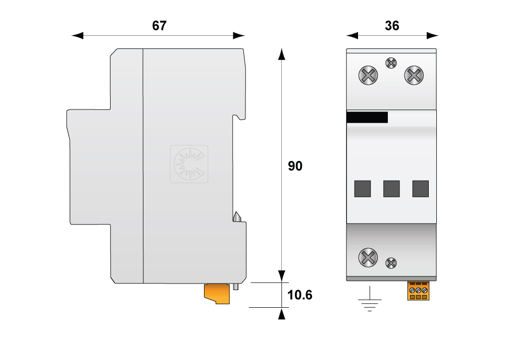
- Dimensions: See diagram
Disconnectors
- Thermal disconnector: Internal
- Installation ground fault breaker: Type S or delayed
- Fuses: Fuses Type gG - 315 A
Standards
- Standards compliance: IEC 61643-11 / EN 61643-11 / Ul 1449
- Certification: EAC
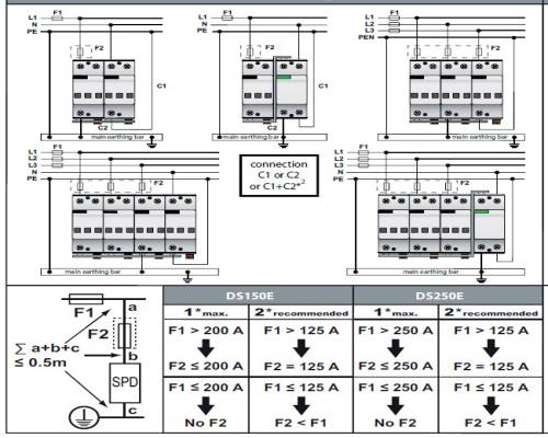
INSTALLATION
DS250E-400 Type 1+2 AC surge protector - 1 pole is connected in parallel on the AC network and must be equipped with external fuses for short-circuit current protection
- The total length of parallel connection wires to AC network must be lower than 0.5 m in order not to increase the protection level (Up) provided by the SPD.
- Wiring is made by screw connections. On some models, a distribution bus can be used.
- The protection wire coming from the SPD must be connected to the bonding bar of the electrical panel. Paralleling the protection wire with phases conductors must be avoided.
- The cross sectional wire must be 6 mm² minimum for Type 2 SPD and 16 mm² for Type 1.
- Local earthing resistance must be in compliance with the electrical rules.


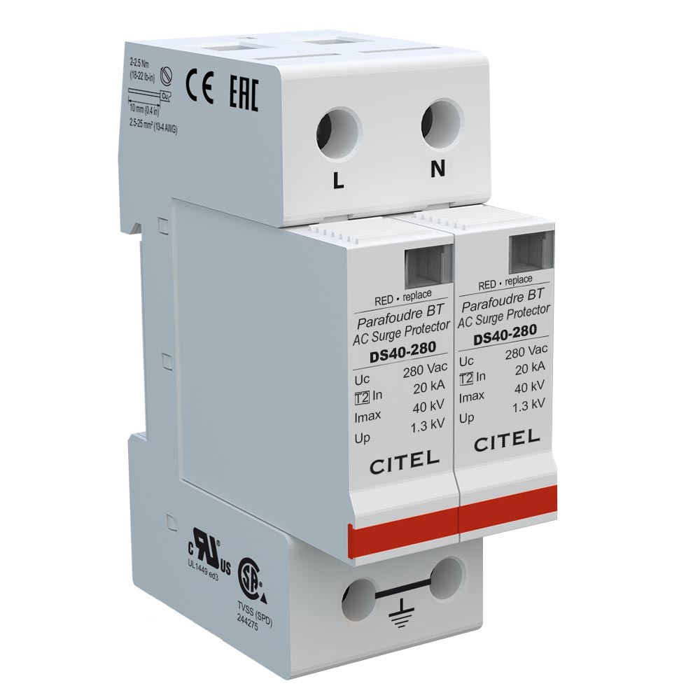
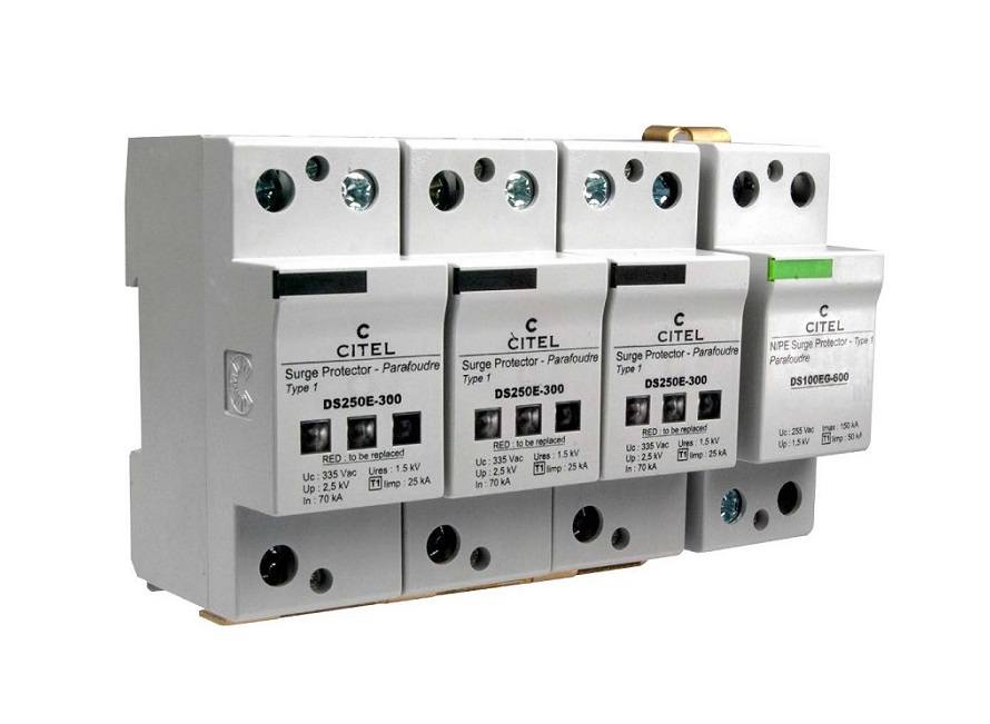
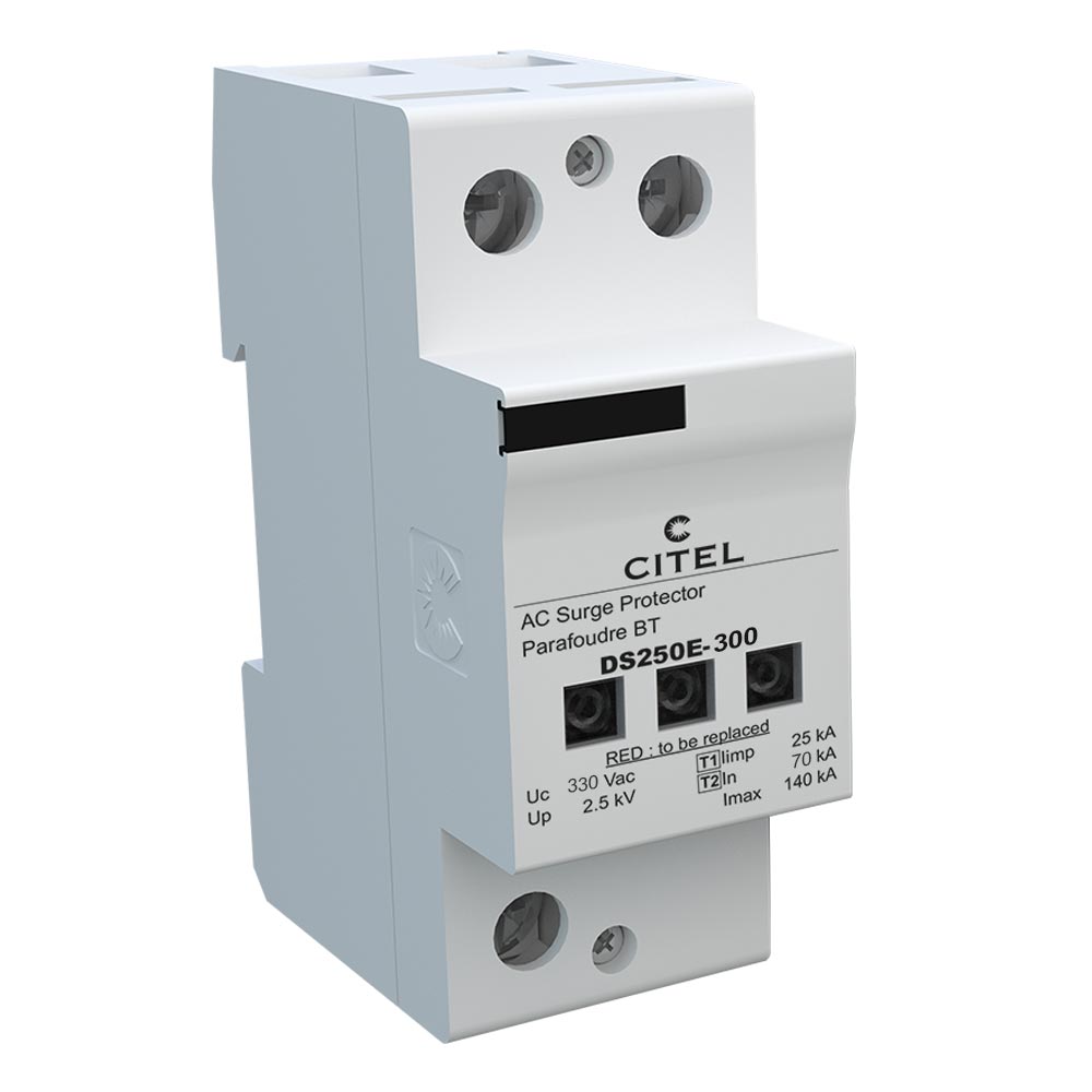
Other Product Series DS250E

Other products in the same category

CART
No products in your cart
Báo Giá Sản Phẩm

THYAN ENGINEERING CO.LTD
- 169/23 Nguyen Thi Muoi, Chanh Hung, Ho Chi Minh City, VietNam
- (84.28) 3850 5678
- info@thyan.vn
- https://thyan.vn/en
- Zip Code: 752800
Sign Up For News
Leave your information and we will contact you!

Copyright © 2022 Công Ty Kỹ Thuật Thy An.


