Explain the parameters of an SPD
Explain the parameters of an SPDs ?
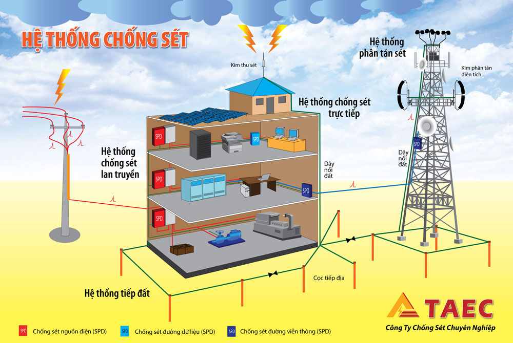
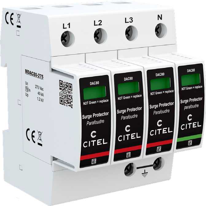
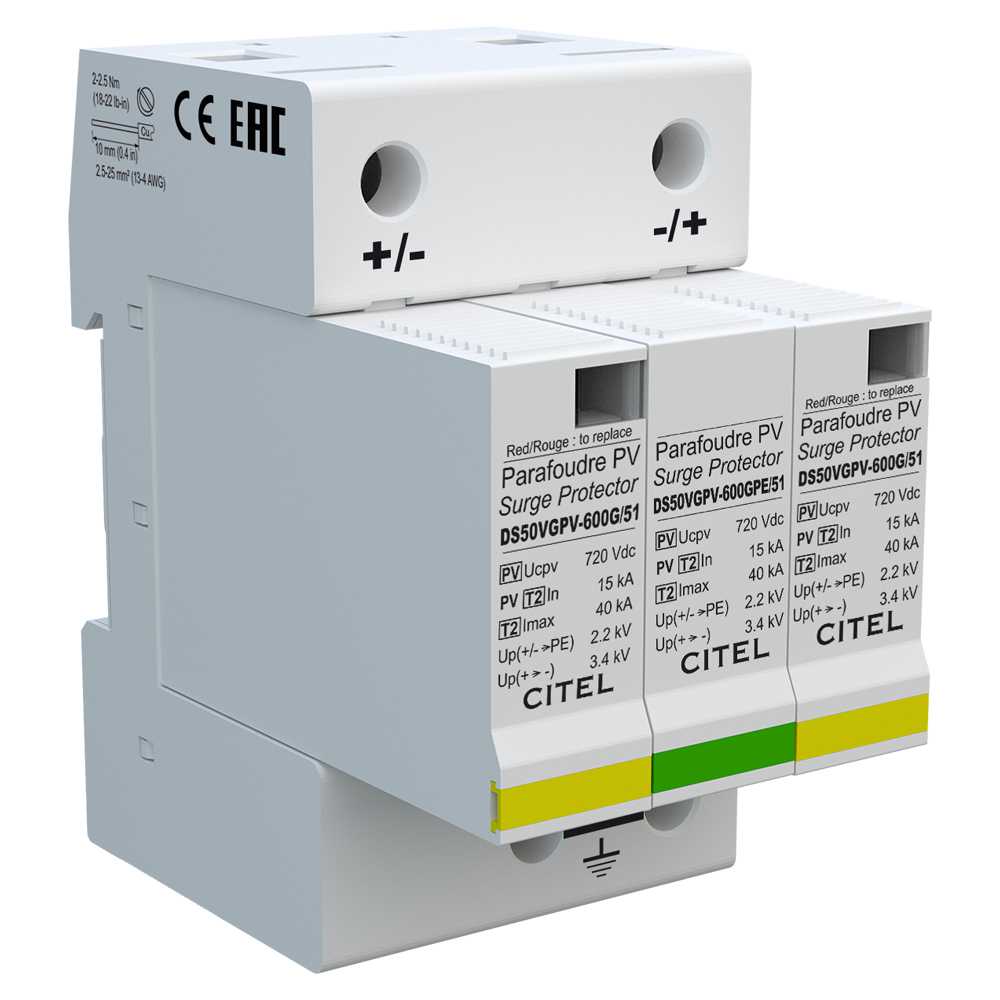
SURGE PROTECTION DEVICE (SPD)
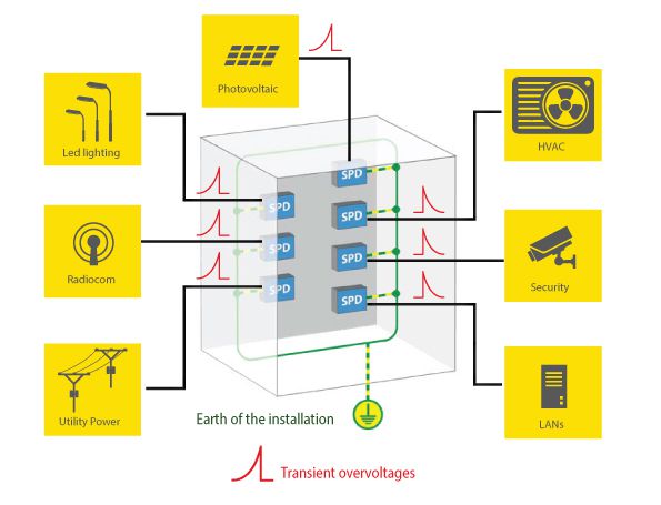
A device intended to limit transient overvoltages and divert dangerous currents. It contains at least one nonlinear component. There are one-port SPDs which are connected in parallel or twoport SPDs which are connected in series.
TYPE OF SURGE PROTECTORS
The AC power surge protectors are split into 3 categories by IEC 61643-11 and EN 61643-11 standards, with the following 3 classes of tests. These different tests depend on the location of the surge protector in the AC network and on the external conditions.
1. Type 1 surge protectors
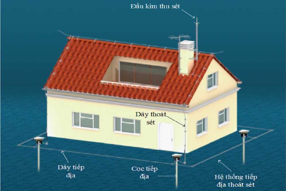
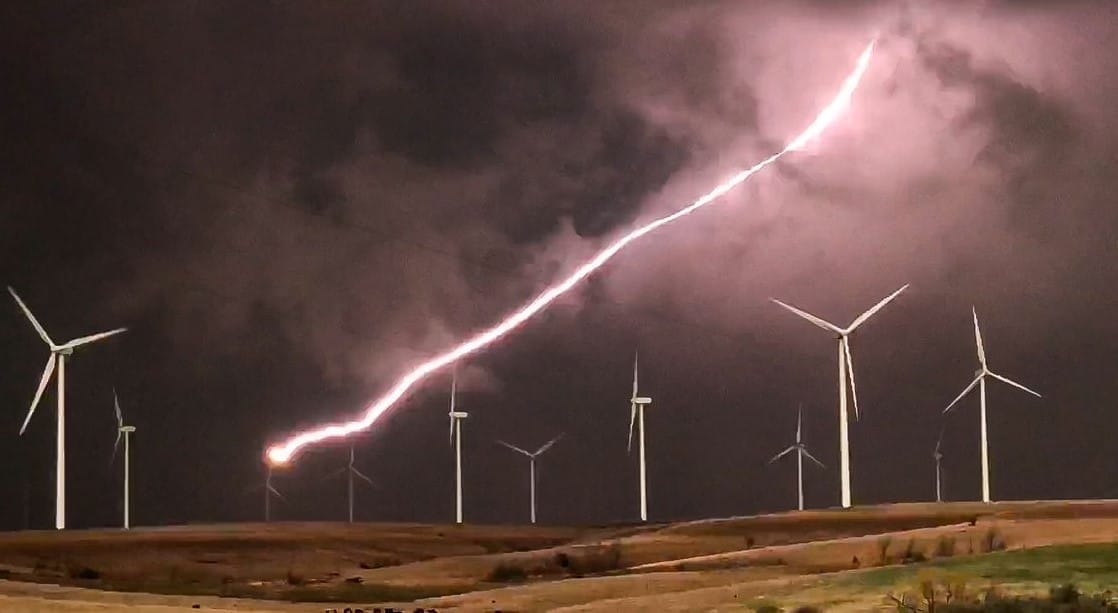
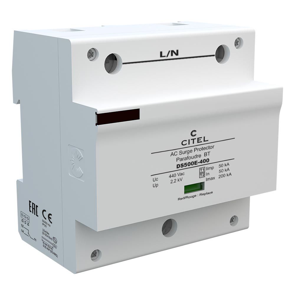
Type 1 surge protectors are designed to be installed where a direct lightning strike risk is high, especially when the building is equipped with external lightning protection system (LPS or lightning rod). In this situation, EN 61643-11 and IEC 61643-11 standards require the Class I test to be applied to surge protectors : this test is characterized by the injection of 10/350 μs impulse current in order to simulate the direct lightning strike consequence. Therefore these Type 1 surge protectors must be especially powerful to conduct this high energy impulse current.
2. Type 2 surge protectors
Type 2 surge protectors are designed to be installed at the entrance of the installation, in the main switchboard, or close to sensitive terminals, on installations without LPS (lightning rods). These protectors are tested following the Class II test from IEC61643-11 or EN61643-11 standards and based on 8/20 μs impulse current injection.
3. Type 3 surge protectors
In case of very sensitive or remote equipment, secondary stage of surge protectors is required : these low energy SPDs could be Type 2 or Type 3 (see «Coordination of surge protector» page 19). Type 3 SPDs are tested with a combination waveform (1,2/50 μs - 8/20 μs) following Class III test.
METHODS OF PROTECTION
An overvoltage protector can be connected Phase to Ground (common), Phase to Neutral (differential), or a combination of both. These connection types are called methods of protection.
OVERVOLTAGE PROTECTOR ALARM
A device that gives a visual indication in the event of protector failure. Some protection devices are fitted with floating changeover contact for remote signalling. The alarm warns of protector disconnection in case of failure to avoid a sustained fault in the system.
NOMINAL VOLTAGE (Un)
The value of the alternating or direct current voltage of the line under normal conditions so that the SPD works correctly.
MAXIMUM OPERATING VOLTAGE (UC)
Maximum voltage that can be continuously applied to the protector.
TEMPORARY OVERVOLTAGE– UT
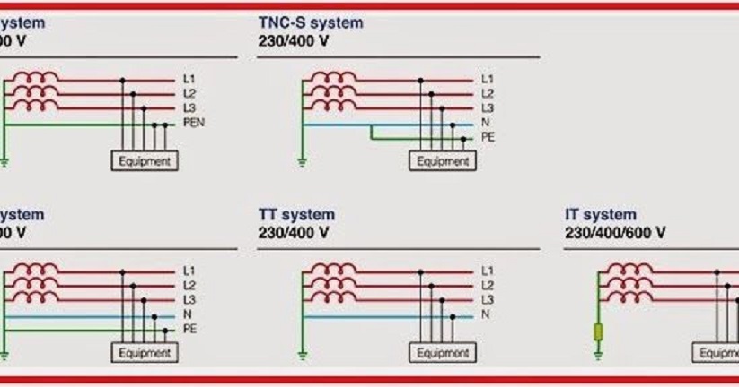
The temporary overvoltage UT (TOV) is the maximum r.m.s. value thesurge protector can withstand during 5 seconds, without failure. Inmany cases , this parameter UT is equal or superior to Uc.An additional test is required for TT AC system, to simulate a temporary«high voltage» overvoltages (TOV) between Neutral and PE(application of 1200 Vac, 300 A for 200 ms): the compliance with thistest requires the use of the CT2 diagram (specific gas tube betweenN and PE).
MAXIMUM WORKING CURRENT (IL)
RMS value of the alternating current or value of the continuous current in a line under normal working conditions so that the protector operates correctly.
NOMINAL DISCHARGE CURRENT In (8/20μs)
The nominal discharge current (In) is the level of impulse current a surge protector Type 1 or Type 2 can withstand repeatedly (15 surges) without destruction.
MAXIMUM DISCHARGE CURRENT (Imax) FOR TYPE 2
The maximum discharge current (Imax), applicable to Type 2 SPD, is the maximum impulse current 8/20 μs a surge protector can withstand without destruction.
IMPULSE CURRENT (Iimp) FOR TYPE 1
The impulse current (Iimp), used in Class I test applicable to Type 1 SPDs, is the maximum impulse 10/350μs current a surge protector can withstand without destruction. This test simulates the effect, on AC power surge protectors, of a direct lightning strike on an installation.
FOLLOW CURRENT (If)
Current supplied by the electrical power system and flowing through the protector after a discharge current impulse. It is expressed in kAeff.
TOTAL DISCHARGE CURRENT – Itotal
Total discharge current flowing in the PE or PEN conductor of a multipolar surge protector.
SHORT CIRCUITS CAPABILITY – Isccr
The surge protection and its associated disconnector (Fuse) are tested at a maximal short circuit current value (ex: 25kA) : This Isccr value needs to be higher than the short circuit value of the network at the installation point.
LEVEL OF PROTECTION (Up)
Maximum residual voltage of the surge protector during an 8/20μs current waveform shot (at the maximum of the In or Iimp declared current).
LEVEL OF PROTECTION AT In : Up-In
Residual voltage of the surge protector during an 8/20μs current waveform shot at a determined value (In or Iimp). This value is lower than the Up Protection level for all the VG type surge protector.
VOLTAGE WITH COMBINATION WAVE (OPEN CIRCUIT VOLTAGE) Uo.c. FOR TYPE 3
This parameter is used only for Class III test, applicable to Type 3 SPD and consists of the injection of a combination wave (1.2/50 μs in open circuit - 8/20 μs in short circuit).
RESPONSE TIME (tr)
Parameter that characterizes the speed of protector activation. It may vary according to the gradient of the applied waveshape, although in general the response time for the varistor is considered to be 25 ns, while for the spark gap it is 100 ns.
FOLLOW UP CURRENT EXTINGUISHING CAPABILITY
When spark gaps or gas discharge tubes ignite, there is a dielectric breakdown, an ignition arc and the resulting short circuit between the two protected conductors. When working voltage conditions return, the referred short circuit and the arc must disappear. The follow up current extinguishing capability refers to the current that the protector is capable of extinguishing by itself in order to return to normal isolation conditions.
SPECIFIC ENERGY W/R FOR TYPE 1 TESTS
The energy dissipated by the impulse Iimp per unit of resistance. This is equal to the power integral in the equivalent resistance during discharge. It is expressed in kJ/Ω or kA2s
BACKUP OVERCURRENT PROTECTION
An overcurrent device (fuse or circuit breaker), which is a part of the electrical installation, located up-stream from the protector and located so as to prevent it from overheating and being destroyed in the event that the protector is not able to interrupt the sustained short-circuit current.
SPARKOVER VOLTAGE OF A VOLTAGE SWITCHING SPD
Maximum voltage value before disruptive discharge between the electrodes in the gap of an SPD.
WORKING TEMPERATURE (ϑ)
Temperature range where the SPD can be used.


