


-
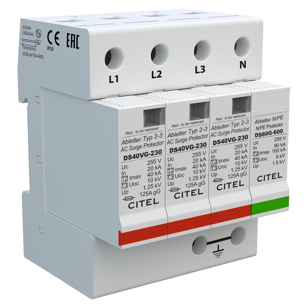
SeriesDAC1-13VG
-
ModelDAC1-13VG-40-275
-
Brand / Made inCITEL / FRANCE
- Type 1 + 2 + 3 AC surge protector
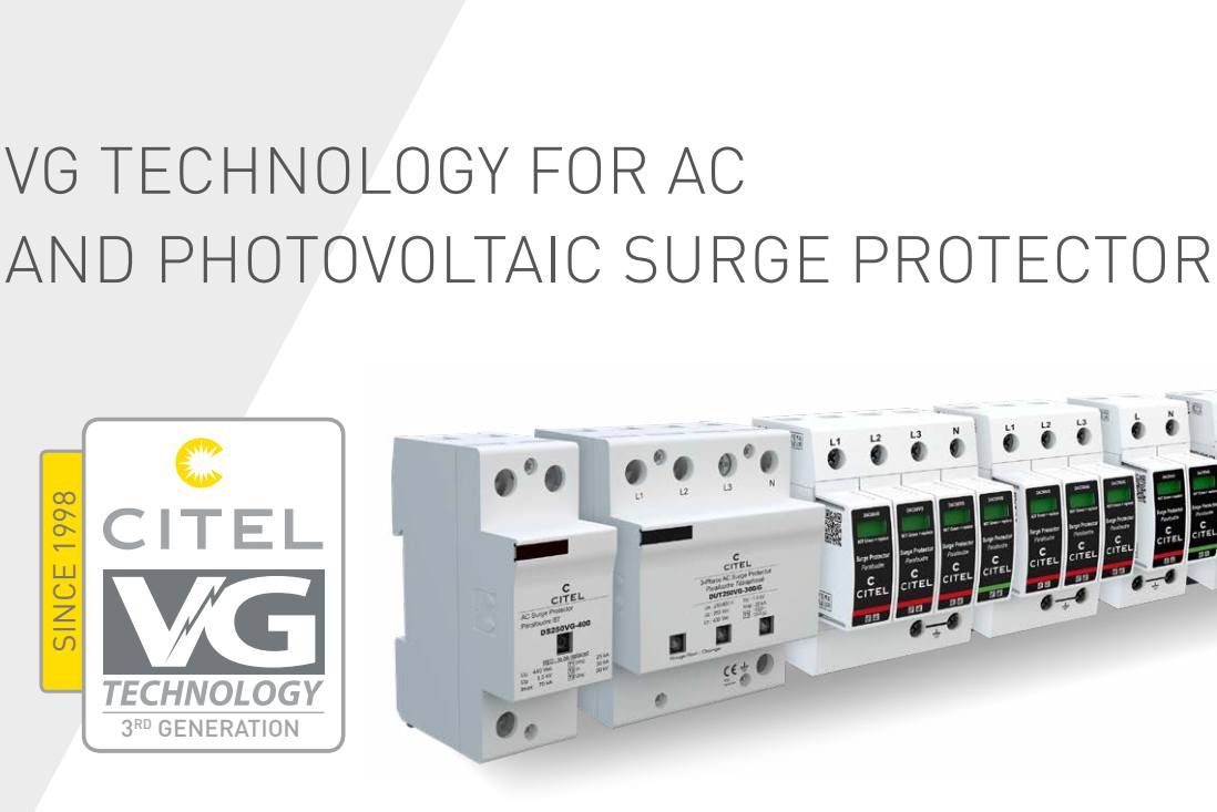
- VG Technology
- Network: 230/400 V 3-phase+N
- In : 20 kA
- Iimp : 12,5 kA on 10/350µs impulse
- No leakage current
- Pluggable module for each phase
- Remote signaling (option)
- Optimized to TOV
- EN 61643-11, IEC 61643-11 certified
- UL1449 ed.5 compliance
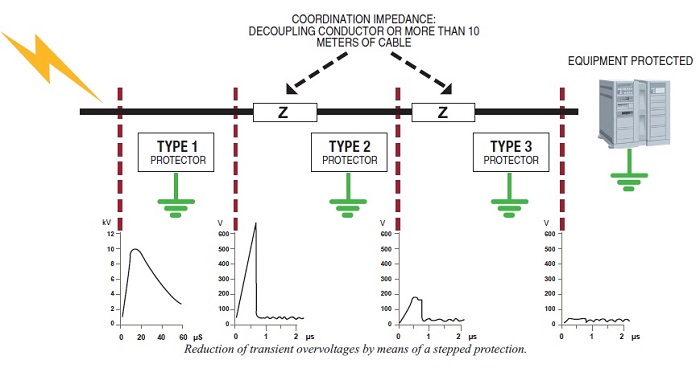
The DAC1-13VG is an extreme duty Type 1+2+3 AC surge protector device designed to protect at the entrance of the electrical installation. This SPD is particularly useful in a high lightning density area where the risk of heavy surge current or even direct strike is high (eg: buildings equipped with lightning rods).
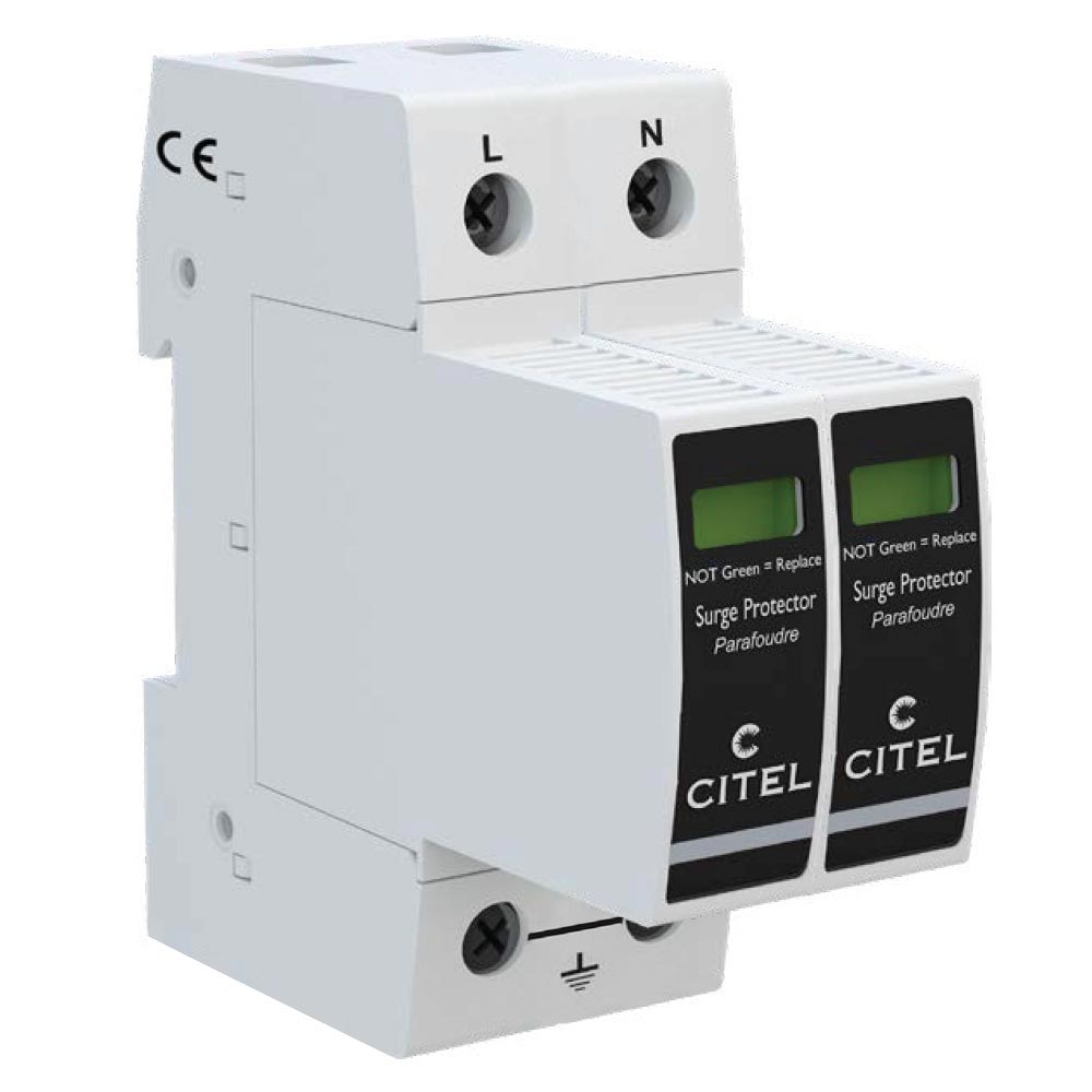
The DAC1-13VG is one-pole SPD and can be used in common mode or common and differential mode.
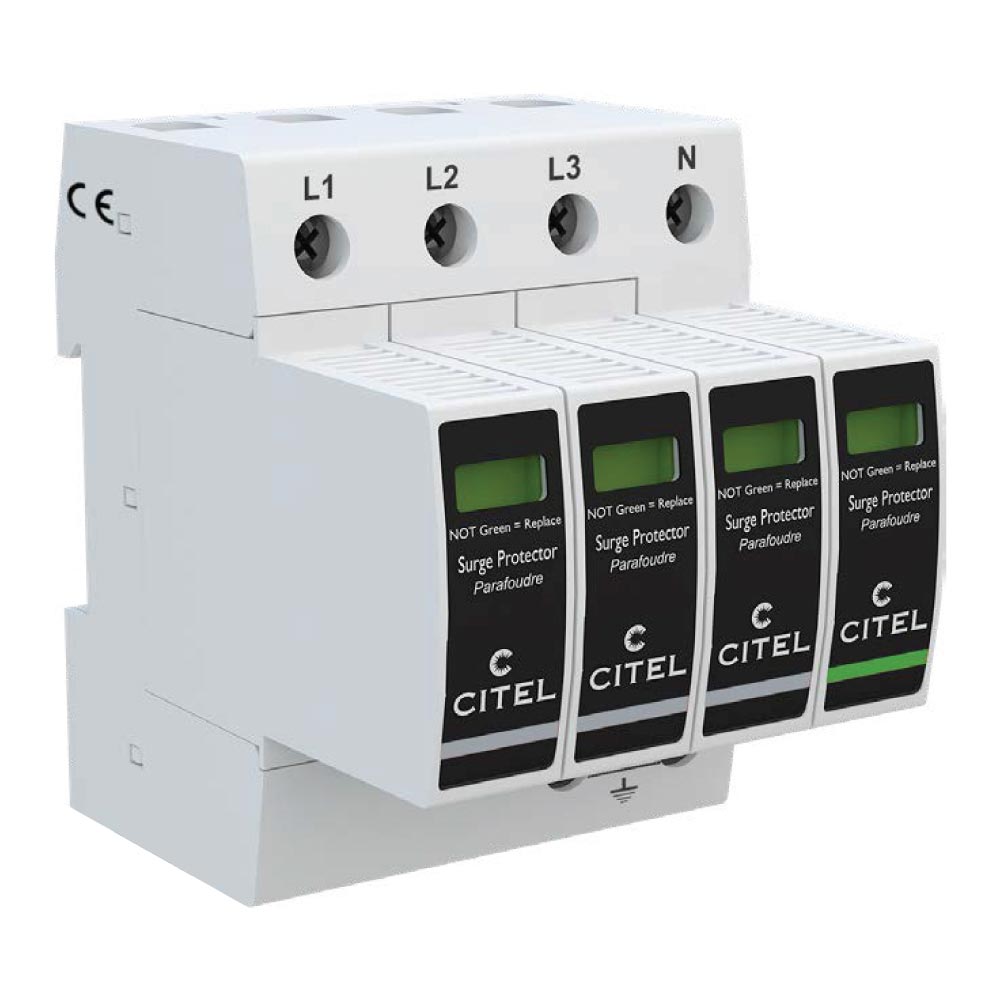
DAC1-13VG AC surge protectors are designed to be connected in multi-pole configuration to protect single-phase, 3-phase and 3-phase+Neutral AC networks, sometimes associated with a dedicated N/PE SPD.
Electrical Characteristics
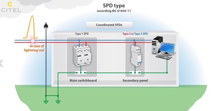
- SPD type (following IEC tests): 1+2+3
- Network: 230/400 V 3-phase+N
- AC system: TNS
- Nominal line voltage Un: 230 Vac
- Max. AC operating voltage Uc: 275 Vac
- Temporary Over Voltage (TOV) Charasteristics - 5 sec (Without disconnection) UT: 335 Vac withstand
- Temporary Over Voltage (TOV) Charasteristics - 120 mn (Without disconnection or with safety disconnection) UT: 440 Vac disconnection
- Temporary Over Voltage N/PE (TOV HT) (Without disconnection or with safety disconnection) UT: 1200 V/300A/200 ms withstand
- Residual CurrentLeakage current to Ground Ipe: None
- Follow current If: None
- Nominal discharge current (15 x 8/20 µs impulses) In: 20 kA
- Max. discharge current (max. withstand @ 8/20 µs by pole) Imax: 50 kA
- Total Maximal discharge current max. total withstand @ 8/20 µs Imax Total: 200 kA
- Impulse current by pole (max. withstand 10/350µs by pole) Iimp: 12.5 kA
- Total lightning current(max. total withstand @ 10/350µs) Itotal: 50 kA
- Withstand on Combination waveform IEC 61643-11 Class III test: 1.2/50µs - 8/20µs Uoc: 6 kV
- Specific energy by pole max. withstand 10/350 µs W/R: 40 kJ/ohm
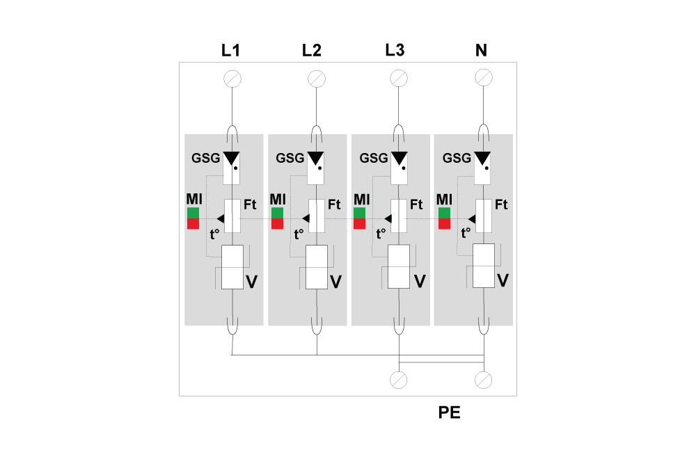
- Connection mode(s): L/PE and N/PE
- Protection level L/PE @ In (8/20µs) Up L/PE: 1.5 kV
- Protection level N/PE @ In (8/20µs) Up N/PE: 1.5 kV
- Residual voltage L/PE at 5 kA @ 5 kA (8/20µs) Up-5kA: 0.7 kV
- Protection level N/PE at 5 kA @ 5 kA (8/20µs) Up-5kA: 0.7 kV
- Admissible short-circuit current Isccr: 50 000 A
- Technology: VG Technology (MOV+GSG)
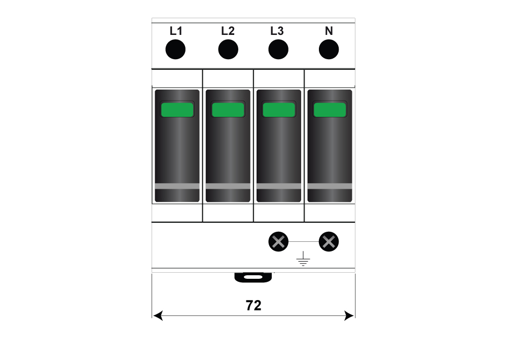
- SPD configuration: 3-phase+N
- Connection to Network: By screw terminals: 2.5-25 mm² (35 mm² rigid)
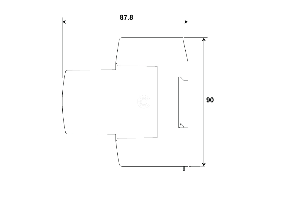
- Format: Plug-in modular box
- Mounting: Symmetrical rail 35 mm (EN 60715)
- Housing material: Thermoplastic UL94 V-0
- Operating temperature Tu: -40/+85°C
- Protection rating: IP20
- Failsafe mode: Disconnection from AC network
- Disconnection indicator: 1 mechanical indicator by pole - red/ Green
- Spare module(s): MDAC1-13VG-275
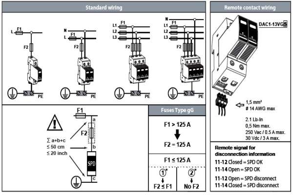
- Remote signaling of disconnection: option DAC1-13VGS-40-275 : output on changeover contact
- Dimensions: 4TE (EN43880)
- Weight 0.653 kg
- Thermal disconnector: Internal
- Installation ground fault breaker: Type S or delayed
- Fuses: 125 A min. - 315 A max. - Fuses Type gG
- Standards compliance: IEC 61643-11 / EN 61643-11 / UL1449 4ed.
- Certification: KEMA / EAC
INSTALLATION
DAC1-13VG-40-275 Type 1+2+3 AC surge protector - 3-phase+N are connected in parallel on the AC network and must be equipped with external fuses for short-circuit current protection
- The total length of parallel connection wires to AC network must be lower than 0.5 m in order not to increase the protection level (Up) provided by the SPD.
- Wiring is made by screw connections. On some models, a distribution bus can be used.
- The protection wire coming from the SPD must be connected to the bonding bar of the electrical panel. Paralleling the protection wire with phases conductors must be avoided.
- The cross sectional wire must be 6 mm² minimum for Type 2 SPD and 16 mm² for Type 1.
- Local earthing resistance must be in compliance with the electrical rules.
Further information can be found in IEC 61643-12 standard (selection and application principles for low voltage SPD).


Other Product Series DAC1-13VG
Other products in the same category

CART
No products in your cart
Báo Giá Sản Phẩm

THYAN ENGINEERING CO.LTD
- 169/23 Nguyen Thi Muoi, Chanh Hung, Ho Chi Minh City, VietNam
- (84.28) 3850 5678
- info@thyan.vn
- https://thyan.vn/en
- Zip Code: 752800
Sign Up For News
Leave your information and we will contact you!

Copyright © 2022 Công Ty Kỹ Thuật Thy An.


