
Surge Protectors for Wind Turbines
Xem nhanh
- PROFESSIONAL SURGE PROTECTION FOR WIND TURBINES
- LIGHTNING PROTECTION ZONE (LPZ)
- TYPICAL REQUIREMENTS FOR WIND TURBINES
- SPD KEY PARAMETERS’ REQUIREMENTS
- DOUBLE-FED INDUCTION GENERATOR (DFIG) SURGE PROTECTION SOLUTIONS
- PERMANENT MAGNET SYNCHRONOUS GENERATOR (PMSG) SURGE PROTECTION SOLUTIONS
- WIND TURBINE SURGE PROTECTION SOLUTIONS
- SURGE PROTECTION FOR WIND TURBINES VIDEO ILLUSTRATION
PROFESSIONAL SURGE PROTECTION FOR WIND TURBINES
The need for Surge Protection Devices
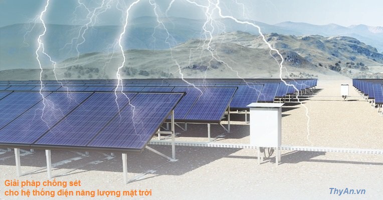
Wind turbines are at high risk of lightning strikes.
Wind turbines are usually located in open areas with excellent wind resources. For example, onshore wind power generation is in protruding terrain such as ridges, while offshore wind power generation is usually located in areas with high ground flash density near coastlines. At the same time, blades of the wind turbines can induce and trigger upward leaders and actively connect with downward leaders in electrostatic fields of thunderstorms, which greatly increases the probability of lightning striking the blades. For this reason, the estimated annual average number of lightning strikes on wind turbines is much higher here than in other areas.
High maintenance costs.
Lightning strikes on a wind turbine may cause blade ablation, a failure of an electrical and control system, and other phenomena. There are many such cases. The yield loss caused by wind turbine maintenance and downtime is very large. For an offshore wind turbine, the maintenance costs are particularly high, and the maintenance period is long. As a result, a large indirect loss will occur due to the shutdown..
The threat caused by a lightning electromagnetic pulse is huge.
Compared with direct lightning strikes, the indirect effect of lightning strikes, namely a lightning electromagnetic pulse (LEMP), is riskier to the electrical and control system of the wind turbine. The main reasons are as follows:
- the probability of lightning strikes on wind turbine blades is high, and the radiated electromagnetic field can cover the entire wind power plant;
- the operating systems of sensitive equipment, such as a main control and a pitch control system, have low immunity;
- the components and parts of the equipment have low capacity to endure LEMP and are prone to breakdown or insulation damage;
- the cable length of the interconnection between the wind turbines and the distance to the grid connection point is long in open areas. The inducted overvoltage can be very significant.
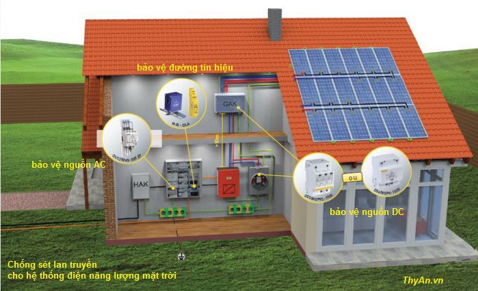
Reasonable installation of SPD is the most effective method.
LEMP is currently the main threat for breakdowns and failures of the electrical and electronic system. At present, the most cost-effective and reasonable main measures are taken: installing a surge protective device (SPD), which discharges the energy matches with the endurance capability of the protected equipment and the immunity of the system, at the boundaries of the lightning protection zones or at the front end of the protected equipment.
Standardizing Requirements
The basic protection method of wind power generation needs to meet the requirements of the basic protection standards of the lightning protection industry: the international standard IEC 62305-1 to 4 and the national standard.
The general and special requirements for wind power industry applications need to meet the requirements of standards IEC 61400-24, which provide requirements for protection of blades, other structural components, and the effects of direct and indirect lightning strike on the electrical and control system while putting forward a request for typical environmental effect factors that the SPD should be able to bear.
Regarding the performance and model selection requirements of the surge protection device, testing and model selection are required in accordance with SPD-related standards IEC 61643.
Division of Lightning Protection Levels
In accordance with IEC 62305, four lightning protection levels are formed, LPL I to IV. For each LPL, the maximum and minimum values of the lightning current parameters that can be protected are specified (see the table below). In accordance with the requirements of the wind power lightning protection standards IEC 61400-24, it is the most reasonable that the wind turbine set and the component system should be divided according to the highest lightning protection level LPLI (except for special requirements).
| First positive return strike | Lightning Protection Level (LPL) | |||||
| Current parameters | Symbol | Unit | 1 | 2 | 3 | 4 |
| Peak current | I | kA | 200 | 150 | 100 | |
| Impulse charge | QSHORT | C | 100 | 75 | 50 | |
| Specific energy | W/R | MJ/Ω | 10 | 5.6 | 2.5 | |
| Time parameters | T1/T2 | µs/µs | 10/350 | |||
LIGHTNING PROTECTION ZONE (LPZ)
Sectioning of a typical wind turbine into LPZ
Defining reasonable lightning protection zones of the wind turbine is a prerequisite for effective surge protection. In general, protection measures, such as a lightning protection system (LPS), the shielding of the wire, and the installation of SPDs, are used to determine the lightning protection zones (LPZ). For details, see Chapter 8.3 of IEC 62305-1.
The following is a schematic diagram * of division of the typical wind turbine into lightning protection zones.
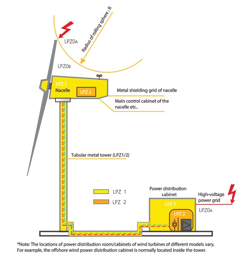
Tower
A tubular metal tower, which is used for a large wind turbine, can be regarded as an almost perfect Faraday cage, owning to its electromagnetic shielding effect. If the electrical connection between the tower and the nacelle is intact and safety grounding is done, the area inside the tower can be defined as LPZ1 or even LPZ2.
Nacelle
The nacelle with glass fiber metal grids has a shielding effect on an external electromagnetic field. The shielding effect is related to the size of the grids. The nacelle is generally defined as an LPZ1 zone. A portion of lightning current may exist in the nacelle to flow through bearings so as to be discharged to the ground via an electric brush, so there may be a radiated electromagnetic field that cannot be shielded by the metal grids.
Power distribution room (box)
The transformer and the grid connection of onshore wind turbines is mostly arranged outside the tower and can be defined as an LPZ1 zone. For offshore wind turbines, the transformer and the grid connection is normally located inside the tower and can be defined as an LPZ2/3 zone.
Hub
The hub mostly consists of a hollow cast iron structure with multiple openings. It provides a magnetic shielding and should be defined as LPZ 1 zone. Inside the hub the pitch control system is located as well as different control system circuits leading to the nacelle.
Defining reasonable lightning protection zones is the prerequisite for effective surge protection.
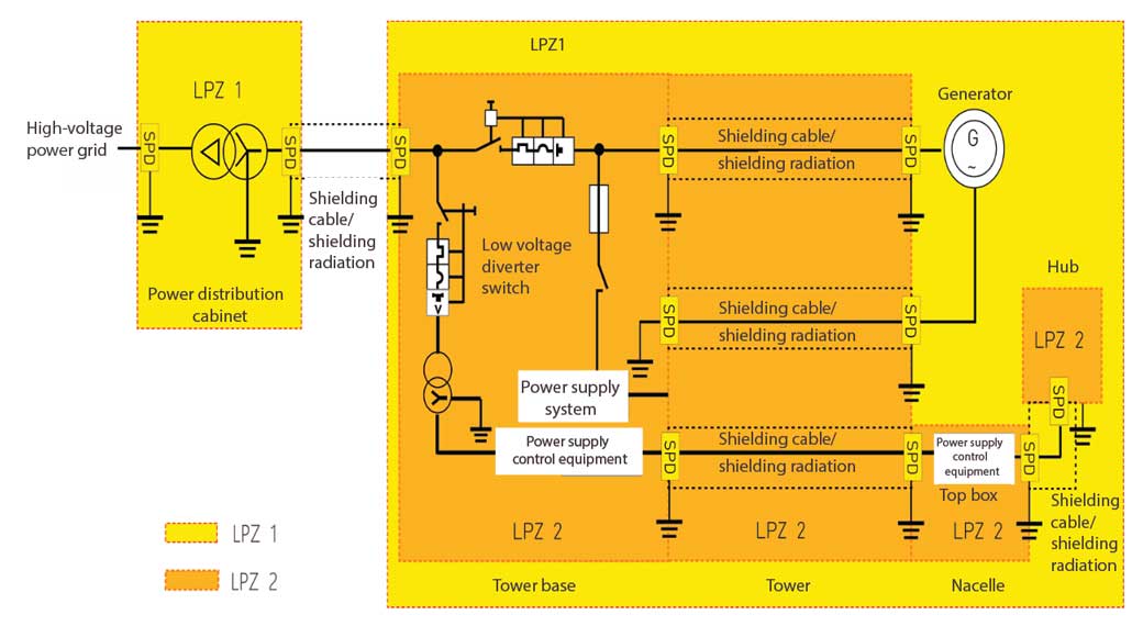
LPZ division and surge protection
The typical LPZ method is used for wind turbines to evaluate and determine the degree of influence of lightning strikes. Components like blades, machines, electrical and control systems can be built to endure this stress.
The test type, discharge capability and installation location of the SPD should be determined according to the influence characteristics of the electrical system at the boundaries of different protection zones. Examples of surge protection measures (SPM) of the electrical system at the boundaries of different protection zones are as follows:
TYPICAL REQUIREMENTS FOR WIND TURBINES
In general, one of three different types of wind turbine sets is used in a wind energy generation system. A doubly-fed induction generator (DFIG), a direct drive generator (PMSG) and a medium-speed generator (a semi-direct drive generator).
Transient Overvoltage Characteristics
Two main types of transient overvoltage may occur during the operation of the wind turbine:
- Transient overvoltage of DFIG converter switching circuit
As a switching device, IGBT is widely applied to converters. When the IGBT modulates and outputs PWM waves to a rotor, the voltage will produce recurring high peaks and transients (harmonics) of the gradient ascending time (du/dt). This harmonic interference will affect the insulation of the rotor generator and the normal operation of the SPD.
- Long cables transmit transient voltage
A converter at the bottom of the tower outputs pulse width modulation waves (PWM), and the distance of transmission of the pulse width modulation waves to a cable of the generator of the nacelle is long. Since long cables have distributed inductance and coupling capacitance, high-frequency overvoltage damped oscillation (harmonics) will be generated.
The possible overvoltage characteristics of the wind turbine are as the standards (the table below). If the endurance capacity of the SPD does not meet the requirements of on-site working conditions, its life expectancy will be greatly reduced.
| Typical voltage characteristcs of rotor side of DFIG | |
| Maximum continuous operating voltage of the system | 750 r.m.s.(±10%), 0~200Hz |
| Transient overvoltage repeatedly superimposed over the operating voltage L-PE | 1.7 kV |
| Transient overvoltage repeatedly superimposed over the operating voltage L-L | 2.95 kV |
| The ascending gradient of repeatedly superimposed overvoltage waveforms | 1.4 kV/µs |
| The switching frequency of the converter | 2000 Hz |
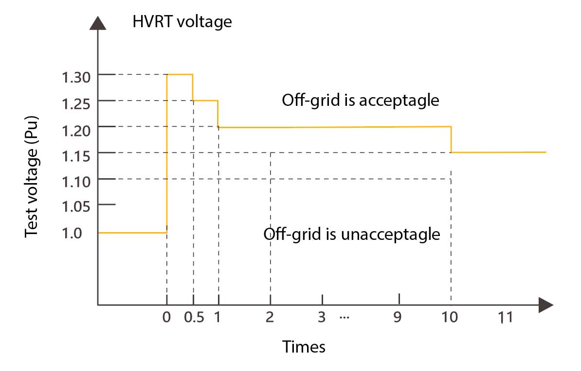
The requirements on HVRT for wind turbines
The high voltage ride-through characteristics given by the relevant standards and shown in the figure below will appear when the electrical system of the wind turbine operates. This type of temporary overvoltage (TOV) will appear in DFIG&PMSG, which may pose a threat to the safe operation of semiconductor equipment including a converter and the like.
CITEL SPD conform to HVRT requirements for wind turbines
| No. |
Operating voltage |
HVRT requirements | CITEL model | SPD parameter | Conclusion |
| 1 | 400/690Vac |
400*1.1=440Vac continuous |
DAC50S-30-760 |
Uc=760Vac continuous |
Satisfied |
| 2 |
400*1.3=520Vac 500ms |
UT=1000Vac 5s withstand |
Satisfied | ||
| 3 |
400*1.1=440Vac continuous |
DAC50S-31-760-2600DC |
Uc=800Vac continuous |
Satisfied | |
| 4 |
400*1.3=520Vac 500ms |
UT=2200Vac 5s withstand |
Satisfied | ||
| 5 | 230/400Vac |
230*1.1=253Vac continuous |
DAC50S-31-320 |
Uc=320Vac continuous |
Satisfied |
| 6 |
230*1.3=299Vac 500ms |
UT=335Vac 5s withstand |
Satisfied |
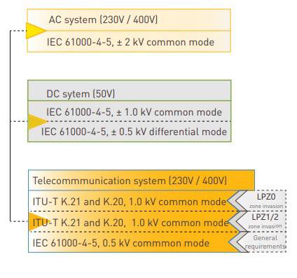
Requirements of the system for the immunity
For the incoming line (there is a portion of intrusive lightning current on the line) connected to the LPZ0A or LPZ0B, AC ports and DC ports of electronic equipment such as the main control system, should be subjected to an immunity test in accordance with the standards IEC 61400-4-5 and IEC 60664-1, the communication port should be tested by reference to ITU-TK.21, K.20 and IEC 61400-4-5.
Environmental Requirements for SPDs Installed in Wind Turbines
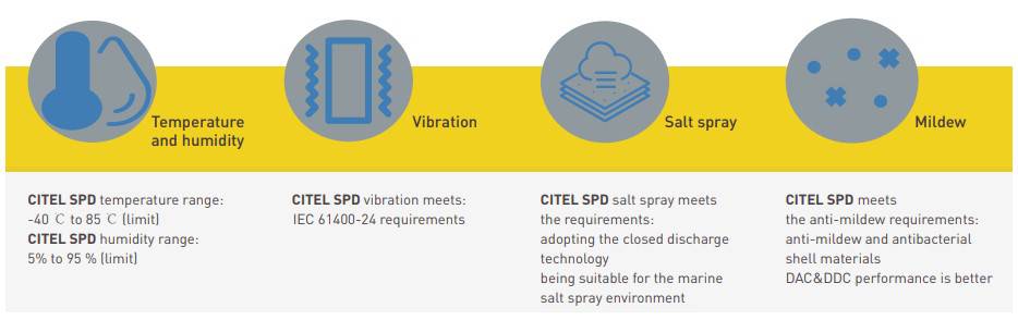
Standard Requirements for Application of SPD in Offshore Wind Power
SPD KEY PARAMETERS’ REQUIREMENTS
Voltage Protection level – Up

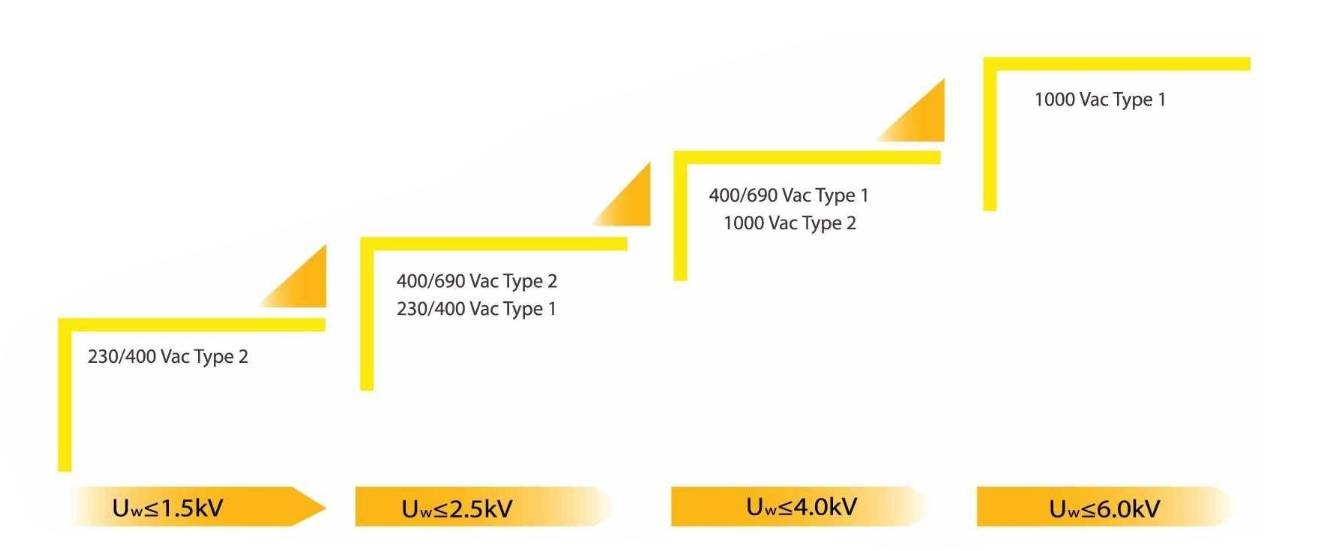
The voltage protection level Up of the SPD used by the wind turbine should consider the rated impulse withstand voltage Uw of the protected equipment (as shown in the table above). If necessary, requirements for the immunity level of an SPD installation system of the wind turbine should be considered at the same time.
Maximum safe continuous operating voltage – Uc
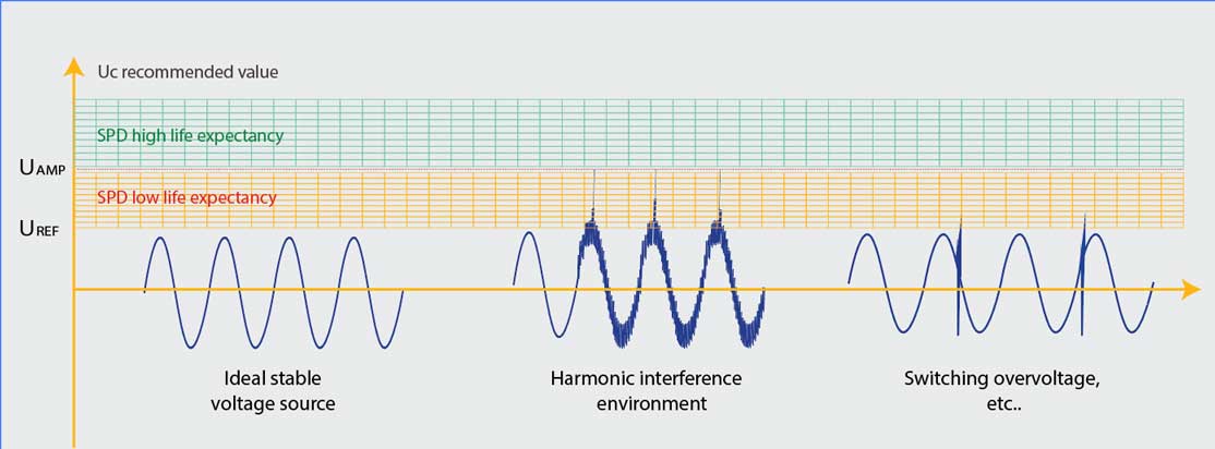
When considering the value of Uc to choose the SPD, the basic requirements such as the operating voltage of a power source at the SPD installation location and the power distribution system should be considered, and then the system reference voltage (UREF) should be determined for model selection. At the same time, wind power applications should especially consider whether there is harmonic interference at the installation location. If yes, the system operating voltage amplitude (UAMP) and the frequency of occurrence need to be considered, some areas with high switching frequency will have switching overvoltage, and some systems need to consider temporary overvoltage resulting from fault voltage (e.g., loss of neutral) and other situations.
As shown in the figure above, an SPD with a selected Uc in the yellow area may operate frequently in the range of the harmonic disturbances. These continuous operations will reduce the lifetime of the SPD. Therefore, it is recommended for wind power applications to select an SPD with an Uc value in the green area, in order to have the service life prolonged.
Wind power SPD designed by CITEL - Better protection, longer service life
Discharge current requirements - In & Iimp
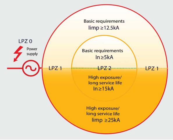
For a wind turbine, a matched discharge type SPD (Type 1+2+3) should be selected, according to the zone where the protection device is located, and meanwhile the exposure of the SPD installation position, the expected service life requirements, the power distribution system, the expected shunt size, and other characteristics should be considered.
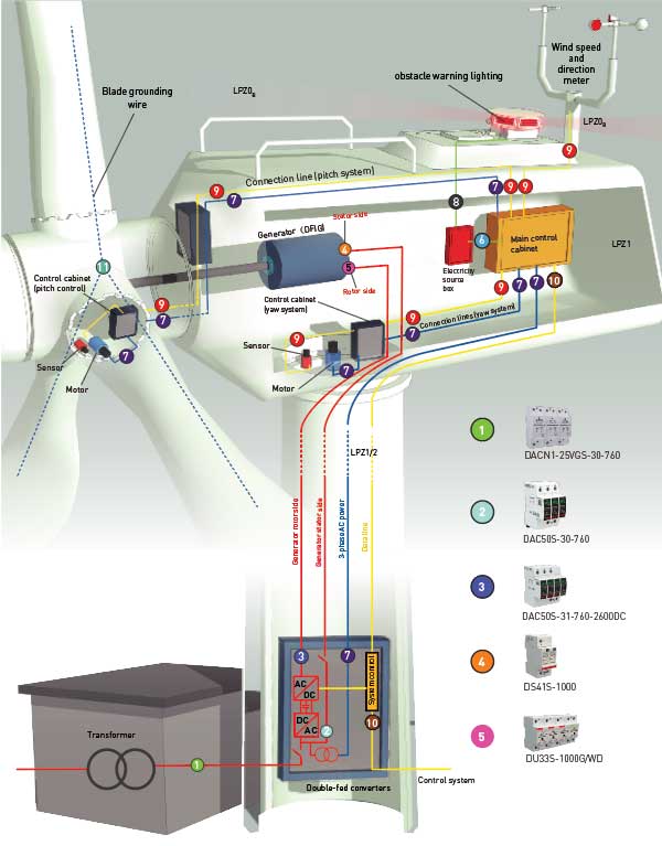
DOUBLE-FED INDUCTION GENERATOR (DFIG) SURGE PROTECTION SOLUTIONS
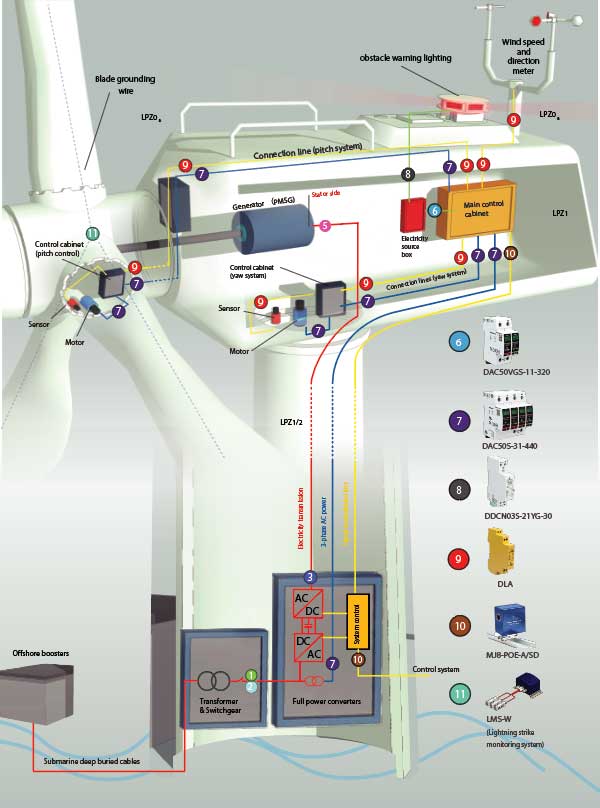
PERMANENT MAGNET SYNCHRONOUS GENERATOR (PMSG) SURGE PROTECTION SOLUTIONS
WIND TURBINE SURGE PROTECTION SOLUTIONS
Example of electrical system for onshore wind DFIG models
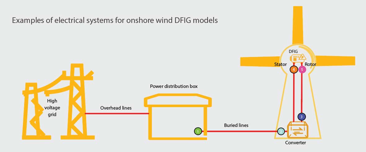

(1) Protection of the low voltage side of the substation
- DACN1-25VGS-30-760: Type 1+2+3 SPD, VG technology, strong discharge capability, high TOV tolerance, long service life, very low residual voltage, monobloc structure.
- DACN1-35VGS-30-440: Type 1+2+3 SPD, VG technology, very strong discharge capacity, long service life, very low residual voltage, monobloc structure.
- DS253VG-1000: Type 1+2+3 SPD, VG technology, strong discharge capability, high TOV tolerance, long service life, low residual voltage, monobloc structure.
(2) Converter grid side protection
- DAC50S-30-760: Type 2 SPD, strong discharge capability, high TOV withstanding capability, MOV protection technology, pluggable module, vibration resistant latching design.
- DS43S-690: Type 2 SPD, high TOV withstanding capability, MOV protection technology, pluggable modules.
CITEL has different surge protection devices for different wind turbines.
Example of electrical system for offshore wind PMSG models
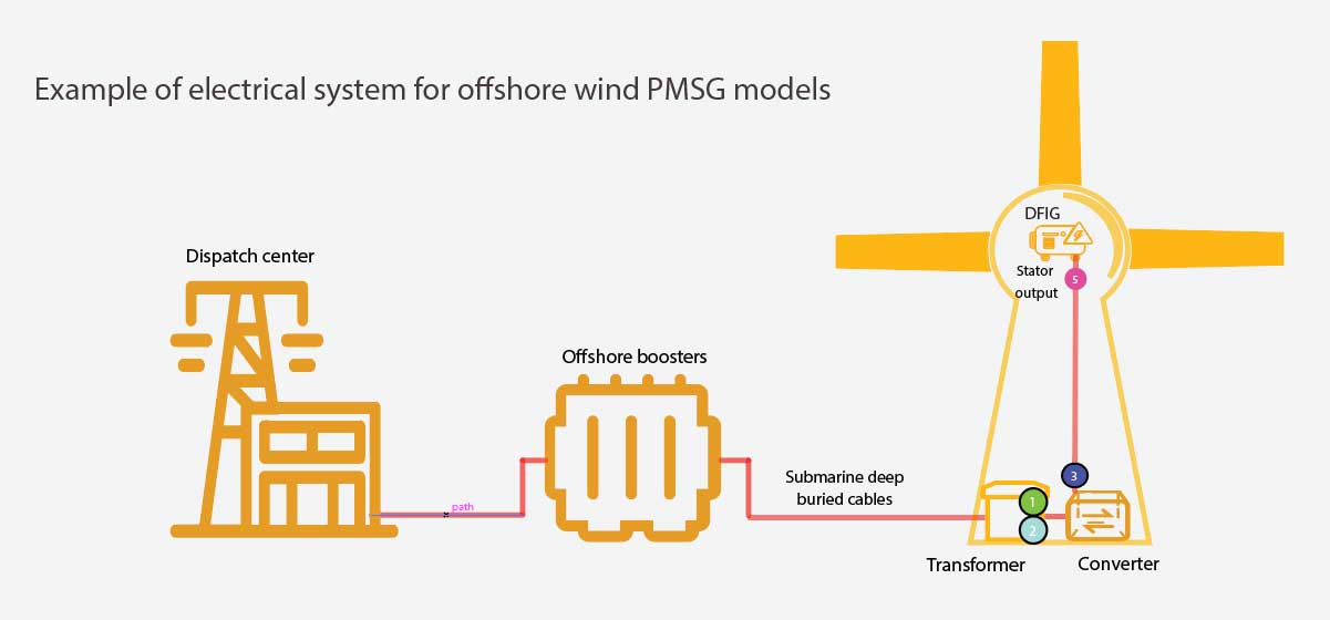
(3) Converter machine side protection
- DAC50S-31-760-2600DC: Type 2 SPD, withstand high harmonic interference from wind turbines, MOV+GSG protection, strong discharge capability, high TOV tolerance, pluggable modules, vibration resistant latching design.
- DS41(S)-1000/WD: Type 2 SPD, high TOV withstanding capability, MOV protection technology, pluggable module, with certain harmonic interference withstanding capability.
(4) Generator protection (DFIG)
- DS41S-1000: Type 2 SPD, high TOV withstanding capability, MOV protection technology, pluggable module, split combination structure to increase insulation capability.
- DU33S-1000/WD: Type 2 SPD, high TOV withstanding capability, low residual voltage, MOV protection technology, single-mode integrated structure to meet vibration and insulation requirements.
(5) Generator protection (DFIG & PMSG)
- DU33S-1000G/WD: Type 2 SPD, withstand high harmonic interference from wind turbines, MOV+GSG protection, high TOV tolerance, single-mode integrated structure to meet vibration and insulation requirements.
Contact THY AN for the best CITEL SPD selection options.
Example of wind turbine main control & pitch system
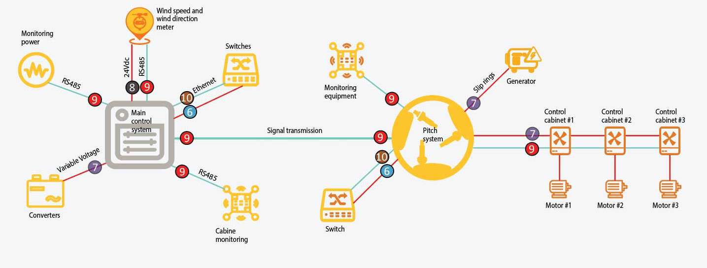
(6) Single-phase AC power 230 Vac
- DAC50VGS-11-320: Type 2+3 SPD, strong discharge capability, long life of VG technology, very low residual voltage, high TOV tolerance, pluggable modules, vibration resistant latch design.
- DS42S-400/G: Type 2 SPD, high TOV withstanding grid fault overvoltage capability, MOV protection technology, pluggable modules.
(7) 3-phase power supply 230/400 Vac
- DAC50VGS-31-320: Type 2+3 SPD, strong discharge capability, long life of VG technology, very low residual voltage, high TOV tolerance, pluggable modules, vibration resistant latch design.
- DS44S-400/G: Type 2 SPD, high TOV withstanding grid fault overvoltage capability, MOV protection technology, pluggable modules.
(8) DC power supply 24 Vdc
- DDCN03S-21YG-30:Type 2+3 SPD, series/parallel installation, common mode & differential mode fine protection, MOV+GDT circuit structure, high load current, compact design, monobloc structure.
(9) Telecommunication signal lines
- DLA/DLA2 series: 1/2 pair line protection, D1&C2&C3 type surge protection, pluggable module, very low residual voltage, common mode & differential mode protection, suitable for RS485, CAN and other communications.
- DLU/DLU2 series: : 1/2 pair line protection, D1&C2&C3 type surge protection, integrated structure, very low residual voltage, common mode & differential mode protection, suitable for RS485, CAN and other communications.
- DLC series:1 pair of line protection, D1&C2&C3 type surge protection, extremely slim design, very low residual voltage, common mode & differential mode protection, suitable for RS485, CAN and other communications.
(10) Data communication network
- MJ8-C6A: RJ45 port for CAT6A, Category D1&C2&C3 surge protection, metal shielded enclosure, common mode & differential mode protection, very low residual voltage.
- MJ8-POE-C6A: RJ45 port, POE&POE+(+):CAT6A, D1&C2&C3 type surge protection, metal shielded housing, common mode & differential mode protection.
- MJ8-POE-A/SD: RJ45 port, fastened rail mount, POE&POE+ (+): CAT5E, metal shielded housing, common mode & differential mode protection.
(11) Lightning strike monitoring system
- LMS-W: Intelligent monitoring of lightning amplitude, lightning strike blade channel and time of occurrence and other parameters can be transmitted to the monitoring system through RS485 to achieve data transmission.
SURGE PROTECTION FOR WIND TURBINES VIDEO ILLUSTRATION


CART
No products in your cart

THYAN ENGINEERING CO.LTD
- 169/23 Nguyen Thi Muoi, Chanh Hung, Ho Chi Minh City, VietNam
- (84.28) 3850 5678
- info@thyan.vn
- https://thyan.vn/en
- Zip Code: 752800
Sign Up For News
Leave your information and we will contact you!

Copyright © 2022 Công Ty Kỹ Thuật Thy An.


